Klang + Ton RSTL DIY Project

The original RSTL design was published as a kit in the December 1987 and January 1988 issues of the German DIY audio magazine Klang + Ton. I’ve searched all over for the entire article, but so far I’ve only found a link to a photo of one page from this topic on a forum for classic KEF speakers:

http://www.hifiloudspeakers.info/speakertalk/viewtopic.php?p=6854

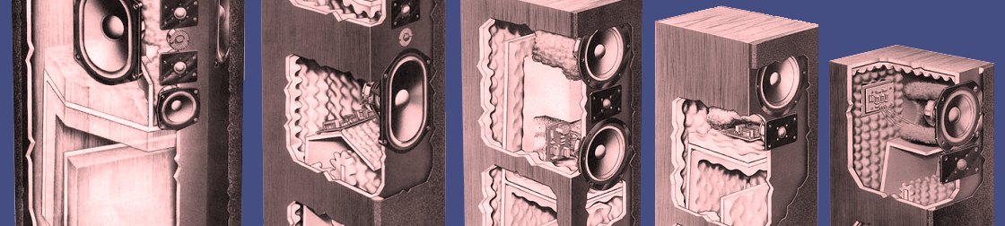
I’ve copied the picture below to make sure this priceless heirloom isn’t lost. I’ll remove it at the request of the original owner. As you can see though it really isn’t clear enough to make out much of the required information, though after pouring over it for some time, I have gleaned a great deal of information from it:

Fact sheet from RSTL plans in Klang + Ton

The "Fact Sheet" from the Klang + Ton plans for the RSTL

My German is not what it used to be – actually I don’t know German at all – so I sat down with Google Translate and came up with this translation of the text:

Fact Sheet

Kit Name

RSTL

Manufacturer

TDL

Construction

TDL/John Wright

Enclosure Type

Transmission Line

Net Internal Volume

Not important for TL

Dimensions in mm

WxHxD 540x1209x492

Number of Drivers

7

Woofer

Ovalbaß (oval)

Midrange

13cm, plastic cone

Tweeter

25 mm, Plastic dome

Super tweeter

19 mm, Plastic dome

Impedance

6 Ω

Efficiency, 1W/1m

Not available

(Power) Rating

Not specified

Recommended amplifier power

Not specified

Crossover

Finished crossover RSTL

Kit price/pair

About 3000 DM

Sales

A. Oberage
Lautsprechervertrieb
Postfach 1562
8130 Starnberg

Bill of Materials

Loudspeaker Drivers TDL
  • 1 woofer 128/25, 16 Ohm
  • 1 woofer 128/20, 8 Ohm
  • 2 mids 130 NS, 11.1 Ohm
  • 2 tweeters 25 DT, 16 Ohm
  • 1 super tweeter 19 DT 06, 8 Ohm
Crossover
  • L1, L2 = 8 mH Iron core
  • L3 = 1.1 mH Air core
  • L4 = 1.7 mH Iron core
  • L5 = 0.25 mH Iron core
  • C1 = 100 μF Electrolytic
  • C2 = 30 μF Electrolytic
  • C3 = 10 μF Film
  • C4, C5 = 4.7 μF Film
  • C6 = 3.3 μF Film
  • C7, C8 = 1 μF Film
  • C9 = 0.47 μF Film
  • C10 = 10 μF Film
  • R1, R2 = 15 Ω
  • R3 = 22 Ω, ceramic, 11W

Cabinet Parts
refer to drawing and text

Exterior walls, 20mm MDF, all dimensions in mm, gross
  • 1 front wall 1209.5×170
  • 2 side walls 1209.5×262
  • 2 side walls 1209.5×306.5
  • 1 back wall 1169.5×500
Interior walls, 12mm MDF, all dimensions in mm, gross
  • 2 MT-Chamber 541×303
  • 1 MT-Chamber 500×303
  • 1 Divider 500×492
  • 1 Divider 500×498
  • 1 MT-Channel 314.5×10⁴
  • 2 MT-Channel above 553×150
  • 2 MT-Channel center 490.5×150
  • 2 MT-Channel below 452×125
Use hardwood 15x15mm, all dimensions in mm
  • 2 616.5
Back wall assembly
  • 2 1169.5
  • 2 184
  • 2 80
Damping Material
  • 5m Rockwool 38cm wide
  • 5 BAF-Wadding, 50×35 cm
  • 100g pure lamb’s wool
Other
  • 16 Allen screws, M5x50mm
  • 16 T-nuts, M5
  • 12 Screws, black, 4x20mm
  • 75 Screws, 3.5x35mm
  • 5m wire, 2.5mm², for wiring
  • Putty to seal the enclosure openings
  • 1 pr gold binding posts

The wood is here!

I’ve decided. The speakers will be Cherry. I’ve taken delivery of 3 sheets of 3/4″ pre-veneered Cherry MDF, 2 sheets of plain 3/4″ MDF, 2 sheets of 1/2″ plain MDF and a sheet of 18 mm Baltic Birch. In each case it is one sheet more than I need for a pair, if I make no mistakes. In the case of the pre-veneered Cherry, there are only millimeters to spare. I’m sure in the TDL cabinet shop this was no problem; my chance of success is zero. So at a cost of over $500.00, I have what I hope will be all the wood I need. They will be considerably better looking than the originals. This picture doesn’t do the Cherry justice – I took the picture right at sunset, so the grain isn’t captured very well.

Photo of Cherry veneer

Sample of pre-veneered MDF to be used in construction

Standing on the shoulders of a giant

In trying to work out an imaginary crossover, I decided the best way to start was to take a similar design and see what CALSOD might do to optimize it. The closest design I could find to my plan (I keep changing my thoughts on drivers) is the Zaph Audio SB12.3. In particular it uses two SB Acoustics SB15NRXC30-8 5″ mid-woofers in an MTM arrangement along with a woofer. Pretty similar to the RSTLM (well, as close as anything gets these days). So I started by attempting to match the SB12.3 mid-woofer modeled response by using the crossover John Krutke specified. I then let CALSOD optimize it and it came pretty darn close to hitting the target:

Graph of predicted response vs target response

Predicted response vs. target response of CALSOD-optimized crossover

Oops

It is very interesting to see what CALSOD does to the component values. Very large or very small values are often a hint to remove a component altogether or change the topology. But if you let CALSOD optimize all parameters, it can come up with some pretty crazy values. Here’s the comparison of the original SB12.3 values to the CALSOD values:

Component values for mid-bass

The CALSOD optimizer chose an unrealistic value for C17.

In this case, it chose a value of over 5000 μF for C17. Ouch. In this case you must mark one or more values FIXED in the optimization so CALSOD won’t try to vary this value. This will likelybe a less optimal solution, but there is not much to be done unless we want to have the huge C17 value.

Also, after the optimizer finishes its magic, we must go back and select actual values that are available to purchase. Of course you can wind (or unwind) your own inductors, parallel resistors and capacitors and so on, but you have to decide just how important it is to have exactly the right value. When I completed this exercise, the final response was:

Graph of frequency response

CALSOD-optimized crossover response using standard parts

This is clearly more ragged at 300 Hz and 1.4 kHz than the original optimized design. It requires tweaking to get just the right tuning, but to a first approximation this is a reasonable approach.

I’m not going to bore everyone with a blow-by-blow analysis of each driver tuning and each change I make along the way. Remember all I’m looking for is proof of concept for my driver choices that I could create a passive crossover with acceptable impedance if I should choose. So this doesn’t have to be perfect – just reasonable.

Thank you

I’d like to thank John Krutke  at Zaph Audio and Madisound for creating and sharing this design. Frankly I don’t expect the RSTLM to ever come close to it in pure sonic terms. I’ve learned a great deal from reading the write-up for it. It is a shining example of what makes this such a great hobby.