I just had to get a peak at what it was going to look like loaded up. Nice! Note also my wonderful assistant, whose support both in the shop and out is instrumental to the success of this project. 🙂
Cabinet

Baffling!
Progress has been slow in recent times as it has been too cold to hang out in the garage. Still, there has been progress, especially on fitting the internal baffling: Notice also that the final section of the midrange line … Continue reading
Progress
An Elephant in the Room
Until now I’ve ignored one of the biggest cabinet problems – the Tang Band woofers are much deeper than TDL/Elac drivers used in the RSTL. How much deeper? Deep enough that I have to cut holes in the vertical dividers between the woofer and midrange sections to allow the woofer magnets room. Of course the woofer and midrange sections should not be open to one another, so I’ll need to build some sort of “cup” to cover over the hole from the midrange side. I didn’t design the hole size via a CAD system, but rather determined it empirically by cutting, trying to seat the woofer and repeat until it fit. I’m confident now I can make it work, but it certainly doesn’t appear in the original plans!
Resurrected
The good news is that I got a chance over the holiday weekend to cut and bevel (but not route) a new woofer panel and to cut and route (except for the TL terminus) the center section. With a number of “L” brackets, pieces are now held in place nice and tight. While it looks like a step backward from 2 months ago, overall it is actually progress. Really. 🙂
Broken!
The astute reader will notice I haven’t posted for the better part of two months. There are a few reasons for this. The first is that I’ve started a new job that takes much more of my time than my old job (60+ hours vs. 40 hours). I love my job at @Pay, but it seriously cuts back on my free time. Secondly, I suffered a series of setbacks in the form of broken pieces (and hence spirits). Both the woofer panels and M-T-ST-T-M panel get quite thin where the driver countersink diameter is the widest. If such a piece falls over flat against a cement garage floor, it can split right in two, taking hours of cutting, routing and so on with it.
I cut the panel shown slightly too narrow, exasperating the problem. A similar fate befell (ha!) a woofer section, it also breaking in two when it happened to fall over. Once supported by the rest of the cabinet structure, this won’t be a problem, but as free-standing structures they are fragile! I am going to reduce the depth of the countersink on the woofers to increase the strength of the panels.
Why can’t it be Round?
It has been a long time again since I’ve posted. Two reasons. One, through the generosity of a visitor, I’ve been digesting some much more detailed information about the original DIY version of the RSTL. When I get done with the translations and cleanup, I’ll post more about what I’ve learned here.
Today though I’ll tell you about a(nother) project that took WAY longer than it should have – creating the countersink template for the woofers. Oh why oh why can’t they be nice and round like most of the other drivers I’ve worked with over the years? Even the line array of ribbons I used in my last speaker were nothing compared to this guy.
I used “Easy Driver Flush-Mounting” in the June 2001 audioXpress as my guide. Suffice it to say Mr. Buike was facing far fewer issues with the Focal woofer in his example than I did with the Tang Band’s irregular shape. The basic idea is to use a flush-trimming bit with a bottom-mounted guide to create a template 1/2″ larger than the driver:
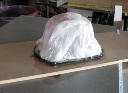
Note the taped-on plastic bag to keep dust out of the driver. Also note the trim bit protruding just to the left of the driver, so it can use the edge of the driver as a guide. I’m going to skip a WHOLE BUNCH of stuff that turned out to be hard here and jump to the next good part. When it is all done, you’re left with a template that is the right shape except it is 1/2″ bigger than the driver on all sides (the width of the trim bit):
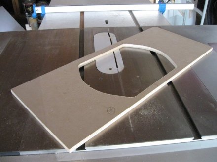
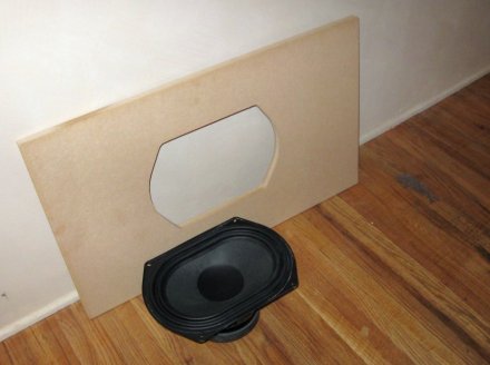
Finally, cut this template down by 3/8″ per side to leave a nice 1/8″ border around the driver:
Notice I left a large border all the way around the cutout, both to leave room to clamp the template and to support the router. A lesson learned (over and over) the hard way.
Crosscut sled project from Hell
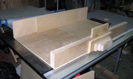
Every big project seems to have something that just doesn’t go well. At all. Well, at least one something. For me, it has been building a crosscut sled for the new table saw. It took me three tries and it still has a variety of problems. For now though, it will work and I can do most of the things I need to with it. It isn’t as pretty as the one on the cover of Fine Woodworking magazine:
However it (finally) works pretty well and is sturdier than my old one. The main problem now is that I need to make cross cuts 45″ long. While I can do this by supporting the piece to the right of the sled, currently there is no way to make repeatable cuts the way I can for short pieces by clamping a scrap against the back fence at the right distance. I’m considering now how to make some sort of extension to allow making these repeatable 45″ cuts, as there are many of them in a RSTL.
The wood is here!
I’ve decided. The speakers will be Cherry. I’ve taken delivery of 3 sheets of 3/4″ pre-veneered Cherry MDF, 2 sheets of plain 3/4″ MDF, 2 sheets of 1/2″ plain MDF and a sheet of 18 mm Baltic Birch. In each case it is one sheet more than I need for a pair, if I make no mistakes. In the case of the pre-veneered Cherry, there are only millimeters to spare. I’m sure in the TDL cabinet shop this was no problem; my chance of success is zero. So at a cost of over $500.00, I have what I hope will be all the wood I need. They will be considerably better looking than the originals. This picture doesn’t do the Cherry justice – I took the picture right at sunset, so the grain isn’t captured very well.
Cabinet exterior design (rough draft)
This is a rough draft of the exterior design for the cabinet. The details aren’t there and some things may change. What it did tell me though is that this speaker can’t be built with a single 4’x8′ sheet of MDF, so I’m looking at 3 sheets for a pair of speakers. Ouch. Well, at least there will be room for error.
- A: Sides of speaker (outside) x2
- B: Sides of speaker (inside) x2
- C: Diagonal fronts (woofers) x2
- D: Front x1
- E: Back x1
- F, G: Inside baffles, not shown
- H: Top, bottom (inside) x2
- I: Top, bottom (outside) x2


