Pretty

I just had to get a peak at what it was going to look like loaded up. Nice! Note also my wonderful assistant, whose support both in the shop and out is instrumental to the success of this project. 🙂

Image of external view of the speaker

Gloria demonstrating the prototype with the drivers mounted

Progress

I’ve made progress the last two weeks – finishing all the front cuts except for the midrange port. I’ve also made progress on the inner baffling (see also An Elephant in the Room).

Speaker cabinet picture

Latest front of view of prototype


Rear-view of cabinet

Rear view display installed internal baffles so far


An Elephant in the Room

Until now I’ve ignored one of the biggest cabinet problems – the Tang Band woofers are much deeper than TDL/Elac drivers used in the RSTL. How much deeper? Deep enough that I have to cut holes in the vertical dividers between the woofer and midrange sections to allow the woofer magnets room. Of course the woofer and midrange sections should not be open to one another, so I’ll need to build some sort of “cup” to cover over the hole from the midrange side. I didn’t design the hole size via a CAD system, but rather determined it empirically by cutting, trying to seat the woofer and repeat until it fit. I’m confident now I can make it work, but it certainly doesn’t appear in the original plans!

Photo of speaker internals

Hole cut in divider between woofer and midrange chambers to accommodate the depth of the woofers

Resurrected

The good news is that I got a chance over the holiday weekend to cut and bevel (but not route) a new woofer panel and to cut and route (except for the TL terminus) the center section. With a number of “L” brackets, pieces are now held  in place nice and tight. While it looks like a step backward from 2 months ago, overall it is actually progress. Really. 🙂

The new prototype shell, 3/4 view


New prototype shell, front view

Broken!

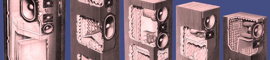
The astute reader will notice I haven’t posted for the better part of two months. There are a few reasons for this. The first is that I’ve started a new job that takes much more of my time than my old job (60+ hours vs. 40 hours). I love my job at @Pay, but it seriously cuts back on my free time. Secondly, I suffered a series of setbacks in the form of broken pieces (and hence spirits). Both the woofer panels and M-T-ST-T-M panel get quite thin where the driver countersink diameter is the widest. If such a piece falls over flat against a cement garage floor, it can split right in two, taking hours of cutting, routing and so on with it.

The top half of what was the prototype M-T-ST-T-M section of the cabinet

I cut the panel shown slightly too narrow, exasperating the problem. A similar fate befell (ha!) a woofer section, it also breaking in two when it happened to fall over. Once supported by the rest of the cabinet structure, this won’t be a problem, but as free-standing structures they are fragile! I am going to reduce the depth of the countersink on the woofers to increase the strength of the panels.

Prototype shell!

I went to a one-day workshop on finishing techniques for wood a few months back. If I take nothing else away, it was worth it for this one thing – the strong advice to always make test samples first. This seemed like just too much work in this case, but finally I decided to go ahead. While there is much more to do, I finally completed an outer shell this past weekend:

Outer shell of

A prototype for the outer shell for the RSTLM. It’s constructed from leftover pieces from my previous speaker project.

While I have a lot more work to do, I’ve already learned so much from the process I’m sold on the advice. Also, it is interesting to finally have a concrete view of the size of these. Until I saw it for real, I didn’t really know what they’d be like.

Articles, Brochures & Reviews, oh my!

A big part of this project has been trying to learn all I can about the original RSTL and RSTL-M. Through the generosity of others, most especially Nick Mellor from the UK, Allegro Sound, Falcon Acoustics and others (both documented and not), I’ve been able to amass quite a collection of literature on the RSTLs. Here is a summary:

  • DIY Articles & papers
    • Klang & Ton / Dec 87-Jan 88 / German
    • Klang & Ton / ?? / Hifi Boxenheft Spezial Nr. 2 / German
    • ?? / ?? / Norwegian? / hifisentralen.no forum
    • A+O Stuffing Instructions / ?? / German / private
  • Reviews
    • Gramophone / Dec 86 / English (UK)
    • Hi-Fi News & Record Review / Jul 88 / English (UK)
    • Stereophile / Dec 89 / English (USA)
    • Gramophone / Apr 96 / English (UK) – RSTL-M
  • White Papers
    • A Monitoring Approach to Loudspeaker Design / May 87 / English (UK)
  • Brochures
    • TDL Brochure (6 pages) / 1988 / English (UK)
    • TDL Reference Series ‘M’ / 1995-6? / English (UK)

Go deep!

In my previous post, I mentioned a discussion about this project on the diyAudio site. One comment referenced an analysis by Martin J. King (http://www.quarter-wave.com/), widely regarded to have the best transmission line modeling software available. He stated that Dr. King had found “Dalines” (what G. L. Augspurger calls “Pipe with Coupling Chamber” ?) inferior to designs. I did find this reference on diyAudio that supports his statement.

Without further ado, here is my model of the Tang Band W8Q-1071F in a RSTL line. Could there be something better? Maybe. Does this strike me as a configuration that will have deep bass? Yes. Am I worried about the dip at 100Hz? Not really – right now I expect I’ll have an active crossover at or below 100Hz, so I’m not at all concerned. Should I go full passive, I’ll have to review my stuffing plans.

Image of TangBand response graph in RSTL

Simulation of TangBand behavior in the RSTL line